作者:VagueCheung,本文转载自:博客园
Vitis 加速基本平台创建
1、Vivado 工程创建,硬件平台bd 图如下所示

1.1、双击Block图中ZYNQ核,配置相关参数
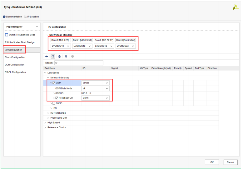
1.1.1、Low Speed 配置,在 I/O Configuration 窗口,配置 BANK0~BANK2 电压为 LVCMOS18, BANK3 电压为LVCMOS33。首先配置 Low Speed 管脚, 勾选 QSPI,并设置为”Single”模式, Data Mode为”x4“, 勾选 Feedback Clk

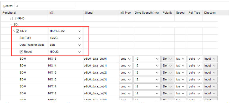
1.1.2、(AXU2CGA 开发板没有 EMMC,不需要勾选此项)勾选 SD 0,配置 eMMC。 选择 MIO13..22,Slot Type 选择 eMMC, Data Transfer Mode 为 8Bit,勾选 Reset,并选择 MIO23。
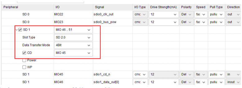
1.1.3、勾选 SD 1,配置 SD 卡。选择 MIO 46..51, Slot Type 选择 SD 2.0, Data Transfer Mode 选择4Bit,勾选 CD,用于检测 SD 卡插入,选择 MIO45
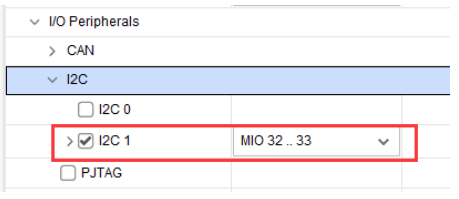
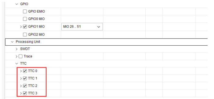
1.1.4、勾选 I2C 1,用于 EEPROM 等的 I2C,选择 MIO 32..33
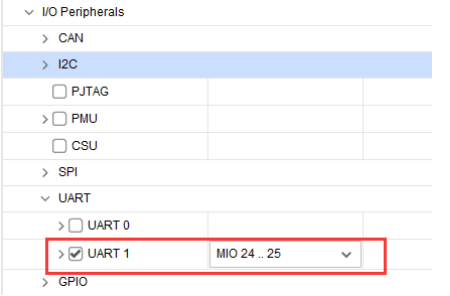
1.1.5、勾选串口 UART 1,选择 MIO 42..43
1.1.6、勾选 TTC 0~TTC 3
1.1.7、High Speed 配置,在 I/O Configuration 窗口,配置 BANK0~BANK2 电压为 LVCMOS18, BANK3 电压为LVCMOS33。 首先配置 Low Speed 管脚, 勾选 QSPI,并设置为”Single”模式, Data Mode为”x4“, 勾选 Feedback Clk
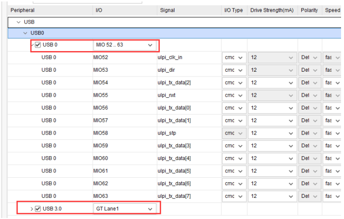
1.1.8、勾选 USB 0,选择 MIO 52..63,勾选 USB 3.0,选择 GT Lane1
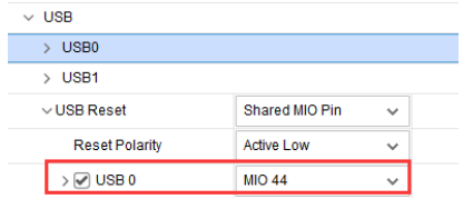
USB 复位选择 MIO 31
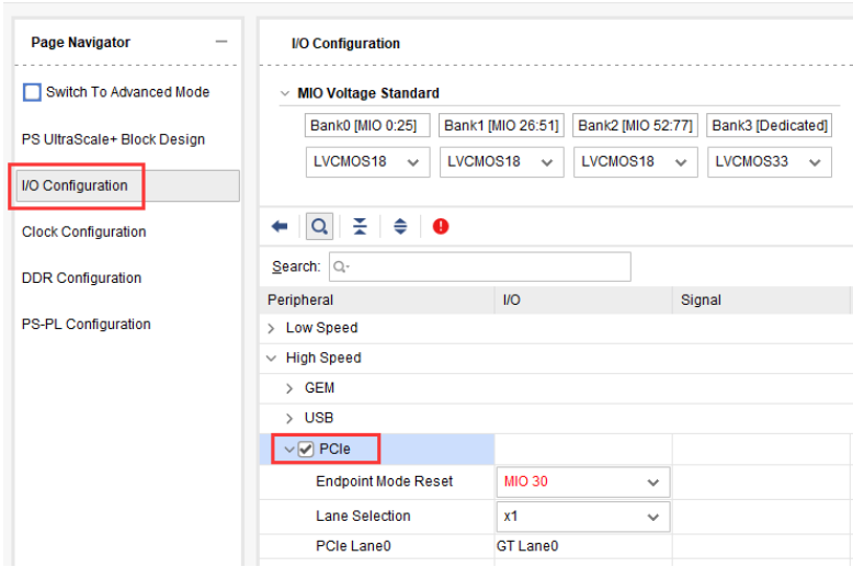
1.1.9、勾选 PCIe
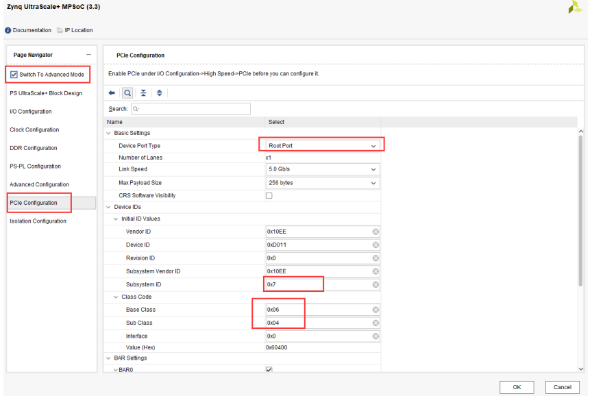
1.1.10、点开 Switch To Advanced Mode,选择 PCIe Configuration,修改以下几个参数,配置为 ROOT模式
1.1.11、回到 I/O Configuration, 选择 GT Lane0, 复位选择 MIO 37; 勾选 Display Port,选择 MIO27..30, Lane Selection 选择 Dual Higher
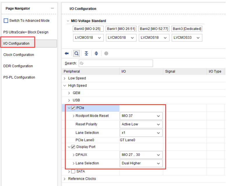
至此,I/O部分配置完毕。
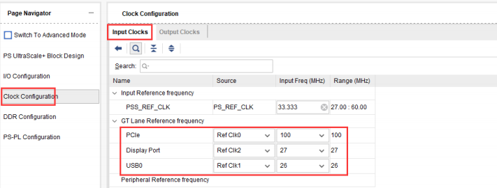
1.1.12、时钟配置,在 Clock Configuration 界面, Input Clocks 窗口配置参考时钟,其中 PSS_REF_CLOCK 为 ARM的参考时钟默认为 33.333MHz; PCIe 选择 Ref Clk0, 100MHz; Display Port 选择 Ref Clk2,27MHz; USB0 选择 Ref Clk1, 26MHz。
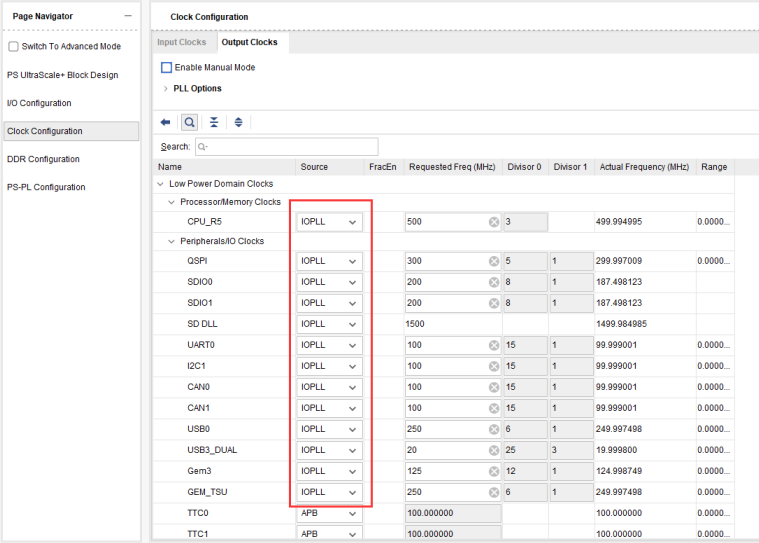
1.1.13、在 Output Clocks 窗口,如果不是 IOPLL,改成 IOPLL,保持一致,用同样的 PLL
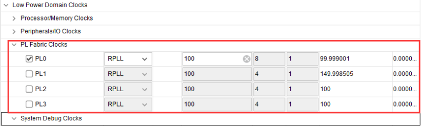
1.1.14、PL 的时钟保持默认,这是给 PL 端逻辑提供的时钟。
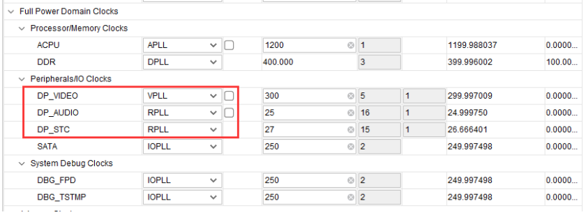
1.1.15、Full Power 部分,其他保持默认,将 DP_VIDEO 改为 VPLL, DP_AUDIO 和 DP_STC 改为RPLL。
最下面的Interconnect修改如下
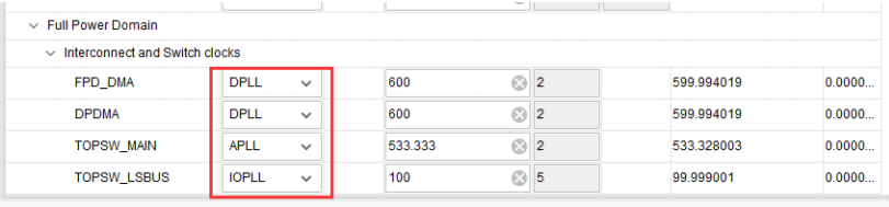
其他部分保持默认,至此,时钟部分配置完成。
1.1.16、DDR 配置,在 DDR Configuration 窗口中, Load DDR Presets 选择”DDR4_MICRON_MT40A256M16GE_083E”
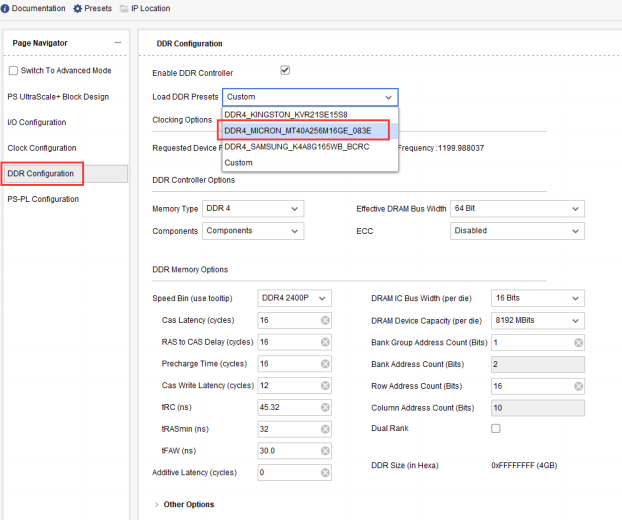
AXU2CGB 开发板配置如下:

其他保持默认,点击OK,配置完成。
至此,ZYNQ核的相关配置全部完成。
1.2、BD设计中添加Clocking Wizard IP核,为了后面定义平台的使用,必须将Clocking Wizard IP核的时钟输出配置为两个以上,本BD设计配置5路时钟输出。
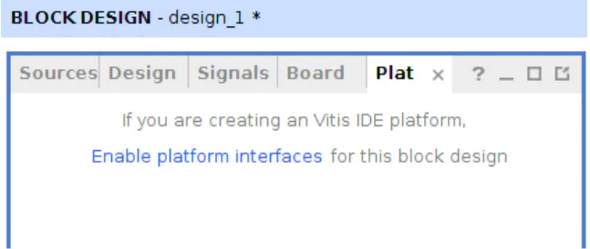
1.3、定义平台(PFM) 接口和属性。 在此定义 Vitis 使用的接口。单击 Vivado 菜单的 Window→Plateform Interface,迚行平台的设定。单击 Enable platform Interfaces 可设置平台。
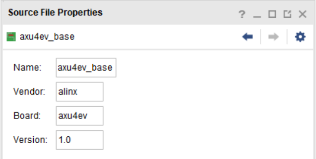
1.3.1、更改 board 的名字,以便在 Vitis 平台上更容易理解。选择了 Platform,将下面的 Board 变更为 axu4ev
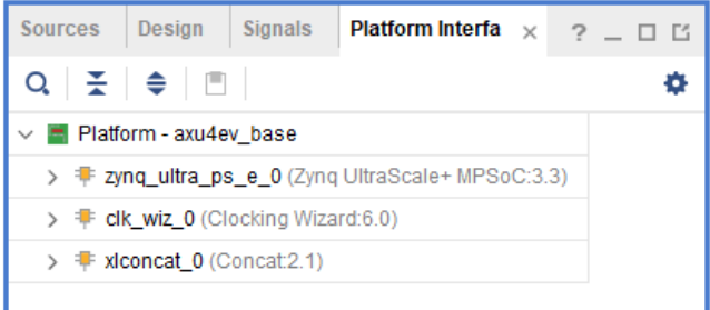
1.3.2、定义可用的接口和端口。各端口用鼠标右键单击,菜单就会出来。双击也可以切换 Enable、Disenable。在 xynq_ultra_ps_e_0 中,将下一个接口、端口设为 Enable。(除此以外是 Dienable)M AXI HPM0 FPD、 M AXI HPM1 FPD、 M AXI HPM0 LPD、 S AXI HPC0 FPD、 S AXI HPC1 FPD、 S AXIHP0 FPD、 S AXI HP1 FPD、 S AXI HP2 FPD、 S AXI HP3 FPD;对于 clk wiz 0 全部用 Enable;对于xlconcet 0,将 In 0~ In 7 设为 Enable。
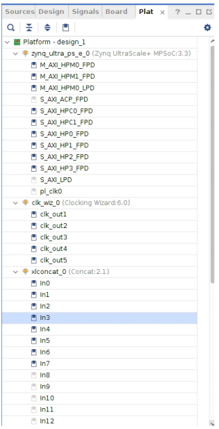
1.3.3、时钟默认值。必须把某个时钟设为默认值。选择 clk out1 后,单击 Plaatform InterfaceProperties 中的 Options 标签,选择 is default。另外,把 id 必须设为 0。可以在 Vitis 中使用的默认时钟。其他时钟依次从 1 开始排列,输入完序号后按回车键确认。
1.4、然后编译生成bit文件
1.5、XRT 环境设置, 在 Tcl 控制台上输入以下命令。因为 Tcl 控制台一行一行输入下列命令。
set_property platform.design_intent.embedded true [current_project]
set_property platform.design_intent.server_managed false [current_project]
set_property platform.design_intent.external_host false [current_project]
set_property platform.design_intent.datacenter false [current_project]
set_property platform.default_output_type "sd_card" [current_project]
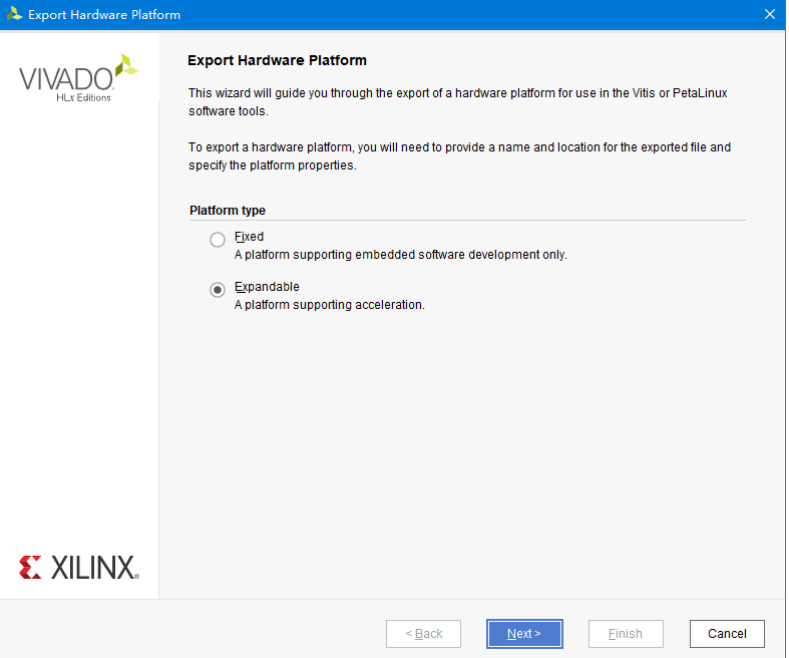
1.6、导出 xsa 文件,选择“Expandable”,这样可以用 vitis 做加速。
1.6.1、Platform state 选择“Pre-synthesis”,再选择“Include bitstream”

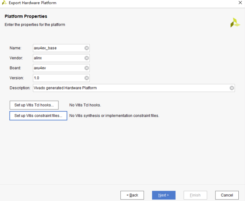
1.6.2、平台属性按下图填写
1.6.3、xsa 文件名默认,保存路径默认即可。
2、Petalinux工程
2.1、在用户目录下,创建一个工作目录,路径中“~”表示用户 home 路径,等效于/home/alinx2020
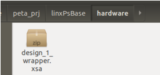
mkdir-p~/peta_prj/linxPsBase/hardware
2.2、将 vivado 导出 xsa 文件拷贝迚 hardware 文件夹下
2.3、进入工程目录
cd~/peta_prj/linxPsBase/
2.4、设置 petalinux 环境变量,运行下面命令,环境变量叧在当前终端中有效,所以后面和petalinux 相关的命令都要在当前终端中输入,关闭后需要重新运行,opt/pkg是用户自定义的petalinux安装路径。
source /opt/pkg/petalinux/settings.sh
2.5、创建 petalinux 工程, 名称为“petalinux”, 类型为“project”, 使用 zynqMP 模板
petalinux-create -t project -n petalinux --template zynqMP
2.6、使用下面的命令进入 petalinux目录
cd~/peta_prj/linxPsBase/petalinux
2.7、配置 Petalinux 工程的硬件信息,硬件信息目录里叧能有一个 xsa 文件
petalinux-config --get-hw-description ../hardware/
2.8、弹出工程配置项界面,如下图, 在“Auto Config Settings”选项中勾选“Device tree autoconfig”、“kernel autoconfig”“u-boot autoconfig”, 然后“Save”、接着“Exit”

2.9、等待配置完成
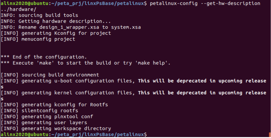
2.10、再一次运行如下命令,进行petalinux配置
petalinux-config --get-hw-description ../hardware/
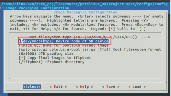
弹出的界面里菜单选项Image Packaging Configuration ->Root filesystem type 选择 EXT (SD/eMMC/QSPI/SATA/USB)
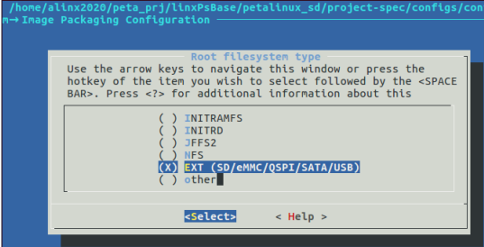
根文件系统路径选择至关重要,如果填错无法启动 Linux, mmcblk 代表 sd 卡和 emmc,mmcblk0p2 代表第一个 mmc 设备第二分区,
如果 emmc 和 sd 卡同时存在, 则 sd 为 mmcblk1,所以这里填写/dev/mmcblk1p2
2.11、修改./project-spec/meta-user/conf/user-rootfsconfig 文件如下
#Note: Mention Each package in individual line
#These packages will get added into rootfs menu entry
CONFIG_gpio-demo
CONFIG_peekpoke
CONFIG_xrt
CONFIG_xrt-dev
CONFIG_zocl
CONFIG_opencl-clhpp-dev
CONFIG_opencl-headers-dev
CONFIG_packagegroup-petalinux-opencv
2.12、修改设备树文件./project-spec/meta-user/recipes-bsp/device-tree/files/system-user.dtsi
/include/ "system-conf.dtsi"
/ {
};
/* SD */
&sdhci1 {
disable-wp;
no-1-8-v;
};
/* USB */
&dwc3_0 {
status = "okay";
dr_mode = "host";
};
&amba {
zyxclmm_drm {
compatible = "xlnx,zocl";
status = "okay";
};
};
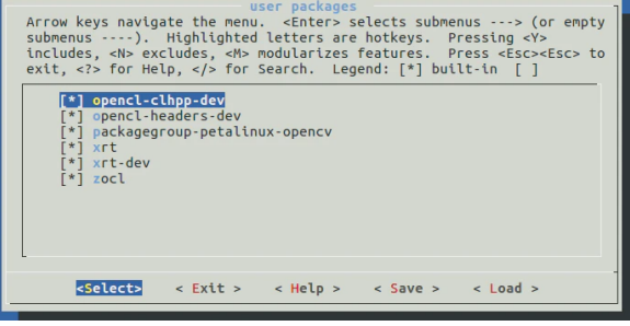
2.13、配置根文件系统
petalinux-config -c rootfs
弹出界面中user packages 全部勾选
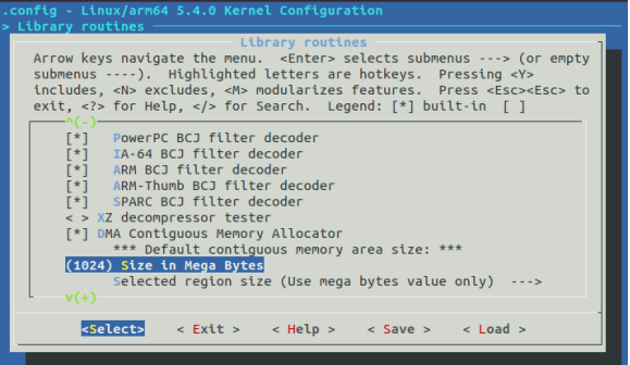
2.14、配置内核
petalinux-config -c kernel
弹出界面中Library routines → Size in Mega Bytes 修改为 1024
2.15、编译petalinux工程
petalinux-build
注:此过程需要连接网络。因需要从github下载源代码。
2.16、构建SDK
petalinux-build –sdk
编译完成后会在petalinux镜像文件夹中自动生成sdk.sh文件,运行该文件,安装SDK环境。记住安装路径,后面Vitis平台配置需要关联次路径。
2.17、新建一个pfm文件夹用于后面构建Vitis平台
mkdir pfm
2.18、在pfm文件夹下建立boot文件夹,然后把petalinux生成的image.ub zynqmp_fsbl.elf pmufw.elf bl31.elf u-boot.elf 复制到boot文件夹
2.19、在boot文件夹建立linux.bif文件,内容如下, 路径需要自行修改
注:.bif 文件创建,使用命令touch name.txt 在使用命令gedit name.bif
/* linux */
the_ROM_image:
{
[fsbl_config] a53_x64
[bootloader] /home/john/peta_prj/linxPsBase/petalinux/pfm/boot/zynqmp_fsbl.elf
[pmufw_image] /home/john/peta_prj/linxPsBase/petalinux/pfm/boot/pmufw.elf
[destination_device=pl]
[destination_cpu=a53-0, exception_level=el-3, trustzone] /home/john/peta_prj/linxPsBase/petalinux/pfm/boot/bl31.elf
[destination_cpu=a53-0, exception_level=el-2] /home/john/peta_prj/linxPsBase/petalinux/pfm/boot/u-boot.elf
}
至此,petalinux工程全部配置完毕。
3、创建Vitis平台
3.1、进入 pfm 文件夹, 启动 vitis 软件
cd ./pfm
运行Vitis2020.1环境 路径自行修改
source /tools/Xilinx/Vitis/2020.1/setting64.sh
打开Vitis工具图形界面
vitis -workspace wksp1
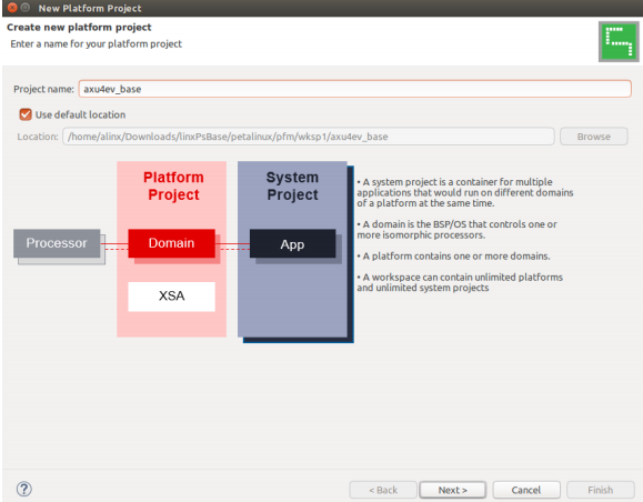
3.2、Vitis 启动后,选择 Create Platform Project。(或从菜单中选择 File→New→Platform Project也可以), Project name 填写 axu4ev_base
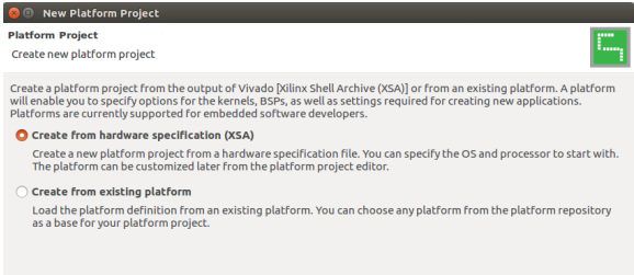
3.3、接下来选择从哪里开始制作平台。因为从 XSA 制作,所以选择 Create from hardware specification(XSA),然后按 Next
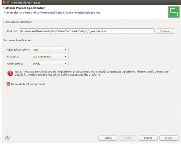
3.4、指定用 Vivado 创建的 xsa 文件, Operatings system 是 Linux, Processor 选择 psu_cortexa53。有一个标志是红色的,没关系。设定后,按 Finish。
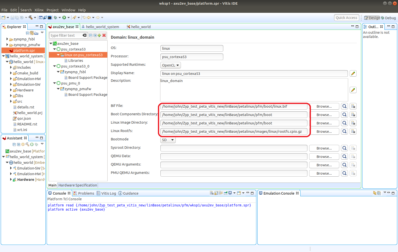
3.5、窗口中有 linux 和 zynqmp fsbl 和 zynqmp pmufw,对于 linux,后面还需要设定。

3.6、linux on psu_cortexa53 里面指定 bif 文件, Boot ComponentDirectory 和 Linux image Directory都指定为上面建立的 boot 目录, LinuxRootfs指定petalinux生成的镜像文件rootfs.cpio.gz,Sysroot 可以暂时不指定, 如果要指定, 可以选择安装后的petalinux sdk sysroots/aarch64-xilinx-linux 文件夹。 点击右上方锤子 开始编译,等待编译完成。
4、测试Vitis加速
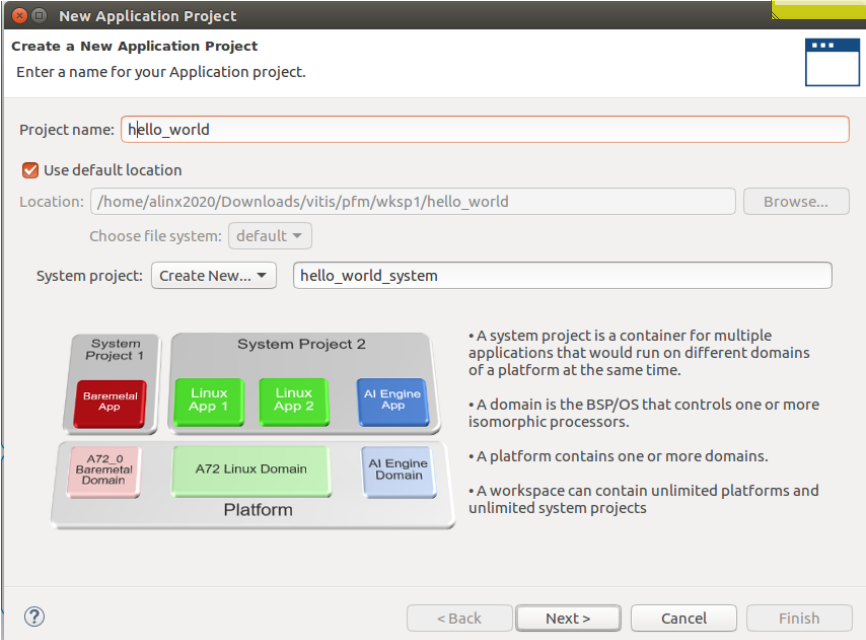
4.1、从 Vitis 菜单中选择 File→New→Application Project。输入项目名称 hello_world,单击 Next
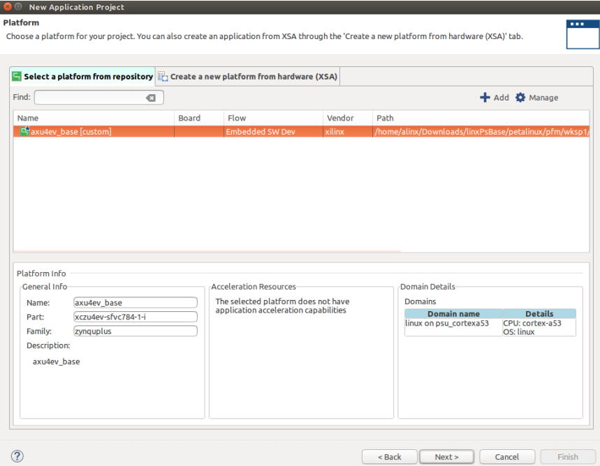
4.2、平台选择刚刚建立的 axu4ev_base
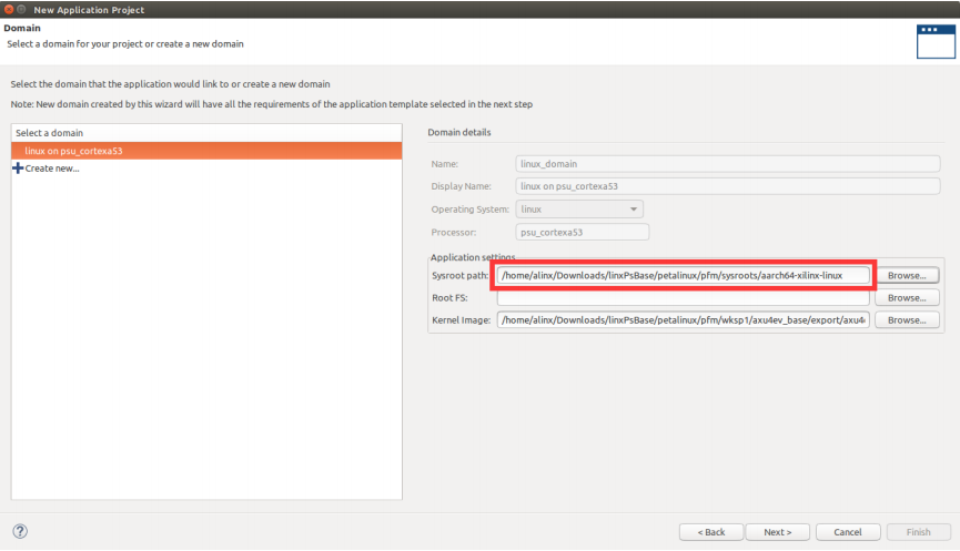
4.3、文件系统选择 petalinux sdk 安装后的文件系统, 点击 Next
4.4、模板就选择 Hello world, 其他模板可能丌能正常加速, 需要修改。

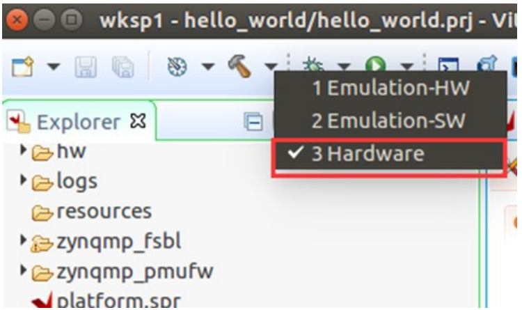
4.5、在锤子下拉菜单中选择 Hardware, 就在要生成在板子上运行的文件, 然后点击锤子编译,时间比较久, 要求虚拟机内存 16G 以上, 否则会出现没有原因的错误。
4.6、编译完成后把 sd_card 文件夹下文件全部复制到 sd 卡第一分区, 同时还需要把petalinux编译生成的镜像文件boot.src文件拷贝到SD卡第一分区,否则板卡启动会卡在某处无法启动,如果没有分区,请参考《SD卡根文件系统制作》

4.7、SD卡第二分区先初除所以内容,再复制 petalinux 生成的根文件系统,路径替换为自己的路径
sudo tar xzvf /peta_prj/linuxPsBase/petalinux/images/linux/rootfs.tar.gz -C /media/john/EXT
4.8、SD 卡插到AXUCGB板子上, 串口终端登录系统, 运行测试程序 export XILINX_XRT=/usr 是必须运行的
cd /media/sd-mmcblk1p1
export XILINX_XRT=/usr
./hello_world vadd.xclbin
串口打印信息会出现“test passed”信息字样。