作者:liuyayong
1、实验方案

图1 实验方案系统框图
2、具体步骤
2.1、vivado工程建立
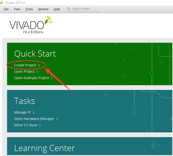
①打开vivado集成开发环境,点击“Create Project”,如下图所示。
②点击“Next”,如下图所示。
③在“Project name”中输入工程名;在“Project location”中选择保存路径;勾选“Create project subdirectory”,最后点击“Next”,如下图所示,注意均不要出现中文。

④选择“RTL Project”,点击“Next”,如下图所示。

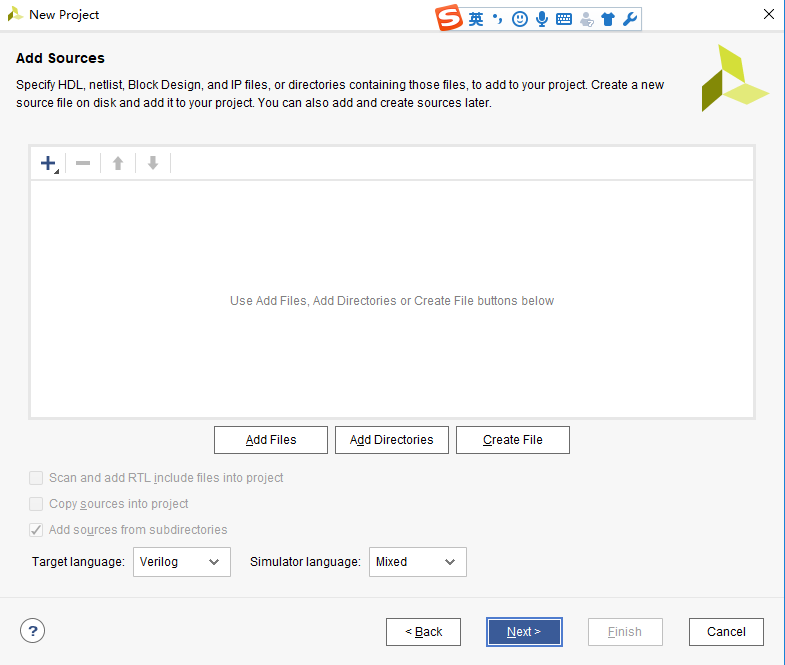
⑤点击“Next”,如下图所示。
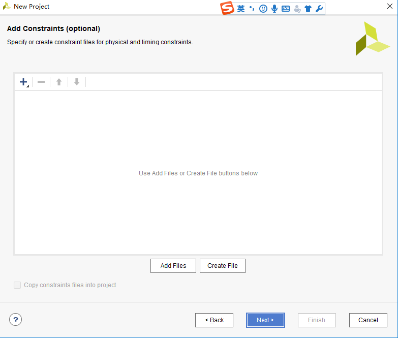
⑥点击“Next”,如下图所示。
⑦输入芯片型号,然后点击“Next”,如下图所示。

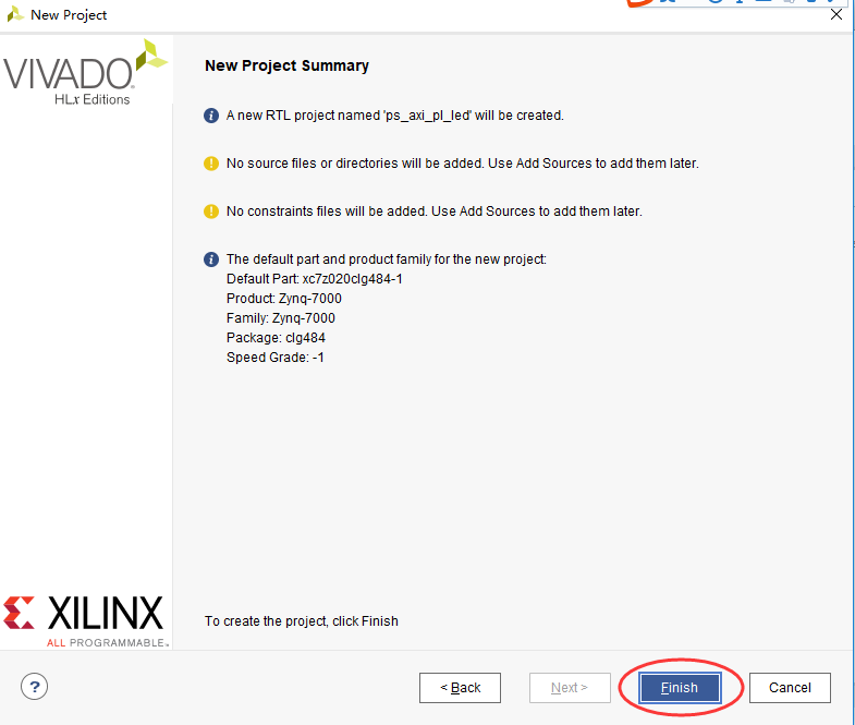
⑧点击“Finish”,完成vivado的工程创建,如下图所示。
2.2、创建一个Block设计
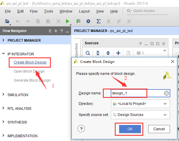
⑨IP INTEGRATOR→Create Block Design,在弹出的对话框中输入设计名,最后点击“OK”,如下图所示。
⑩点击“+”,在搜索框中输入“zynq”找到“ZYNQ7 Processing System”,双击就可以将ZYNQ处理器添加到设计中了,如下图所示。

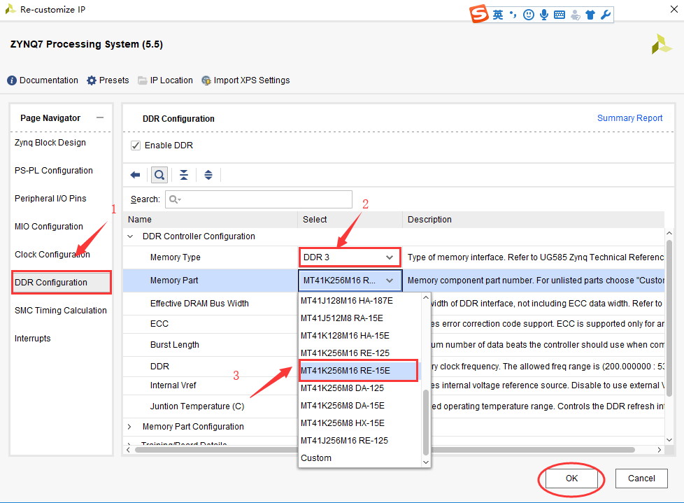
⑪双击ZYNQ→DDR Configuration→DDR Controller Configuration→DDR3,在Memory Part下拉菜单中根据自己板子上的DDR来选择相应的DDR3,本实验所用到型号:MT41K256M16 RE-15E,最后点击“OK”,如下图所示。
注意这里的DDR3并不是和板子上的DDR3严格对应,而是参数最接近的型号,有时候实验不通的话,问题往往出现在这里,可以多试几个。
⑫点击“Run Block Automation”如下图所示。
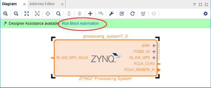
⑬在弹出的选项中保持默认,点击“OK”,即可完成对ZYNQ7 Processing System的配置。
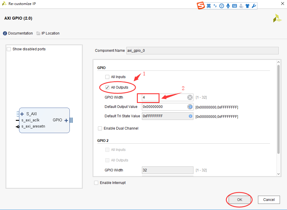
⑭按照添加ZYNQ7 Processing System的方法,继续添加AXI GPIO,然后双击AXI GPIO,打开AXI GPIO配置对话框,由于只有输出4个led灯,故而按照下图对其进行设置,最后点击“OK”确认。

⑮点击“Run Block Automation”即可完成对AXI GPIO的设置,如下图所示

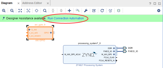
⑯点击“Run Connection Automation”。
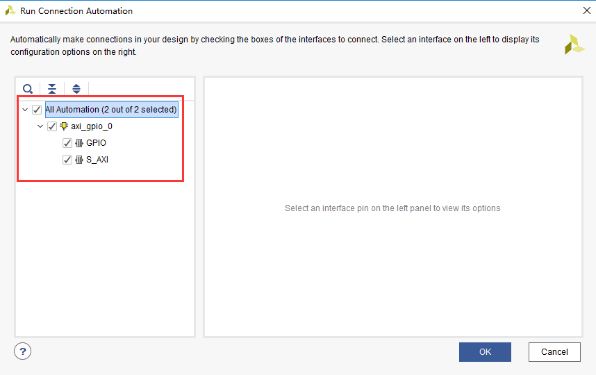
⑰在弹出的对话框中按照下图所示配置,然后“OK”确认。
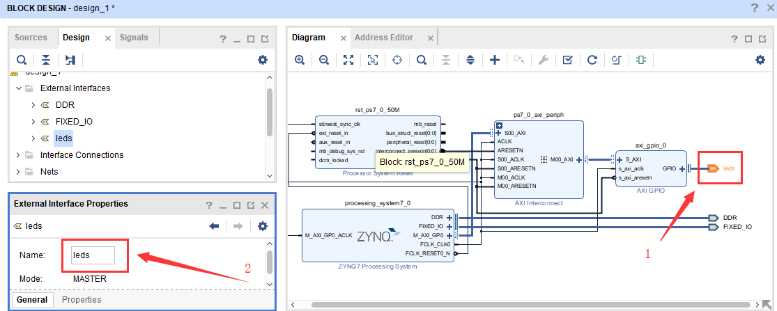
⑱最后生成如下的框图。

⑲在框图中点击gpio引脚,在左边的“External Interface Properties”给gpio起名leds,如下图所示。
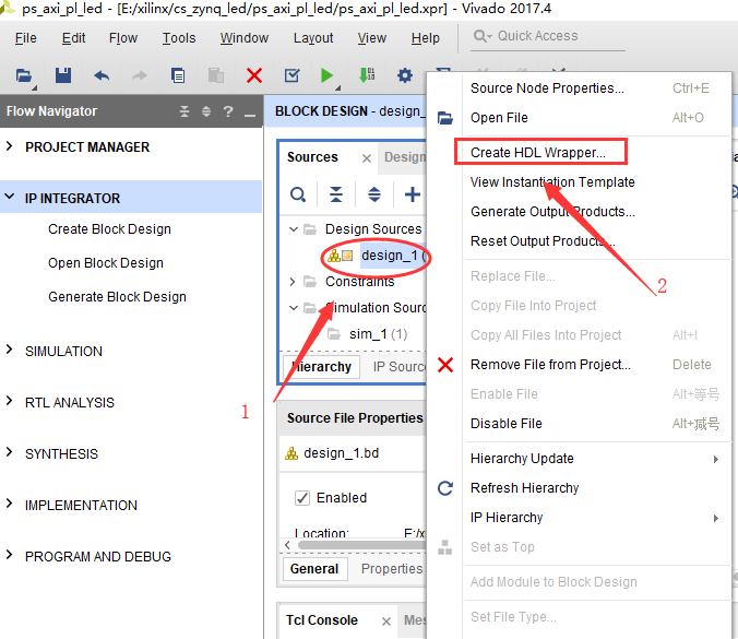
⑳source→design_1→create HDL wrapper…,如下图所示。
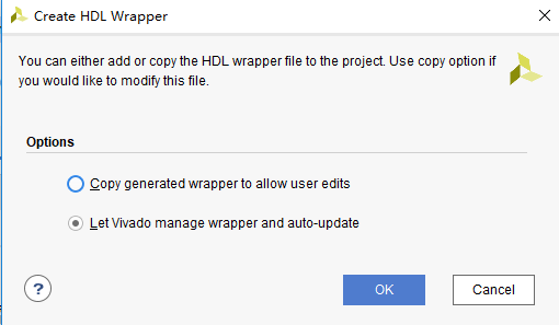
21在弹出的对话框中,保持默认,点击“OK”确认,如下图所示。
22至此,可生成HDL文件,如下图所示。

2.3、.XDC文件约束PL管脚
23在source目录下,点击“+”,在弹出的对话框中选定“Add or create constraints”最后点击“Next”,如下图所示。

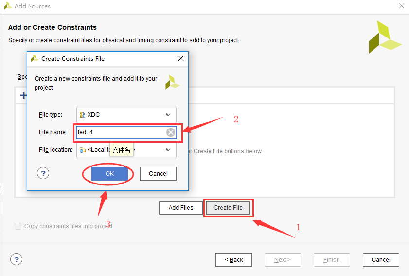
24点击“Create File”,在弹出的对话框中给约束文件命名,点击“OK”确认,如下图所示。
25点击“Finish”,完成约束文件的创建。

26打开新建的约束文件,进行如下的管脚分配。

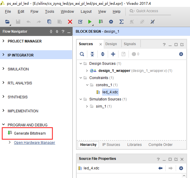
27产生bit文件。
2.4、SDK程序编写
28File→Export→Export hardware…,在弹出的对话框中勾选“include bitstream”,点击“OK”确认,如下图所示。

29File→Lauch SDK,在弹出的对话框中,保存默认,点击“OK”,如下图所示。

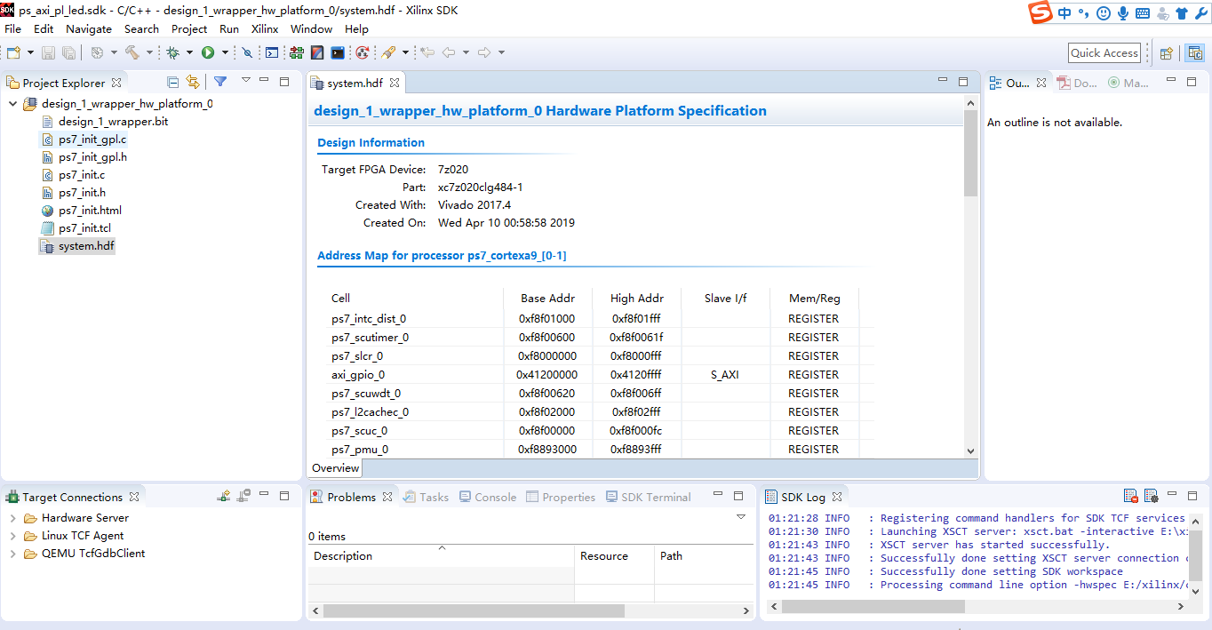
30至此,打开SDK开发环境,如下图所示。
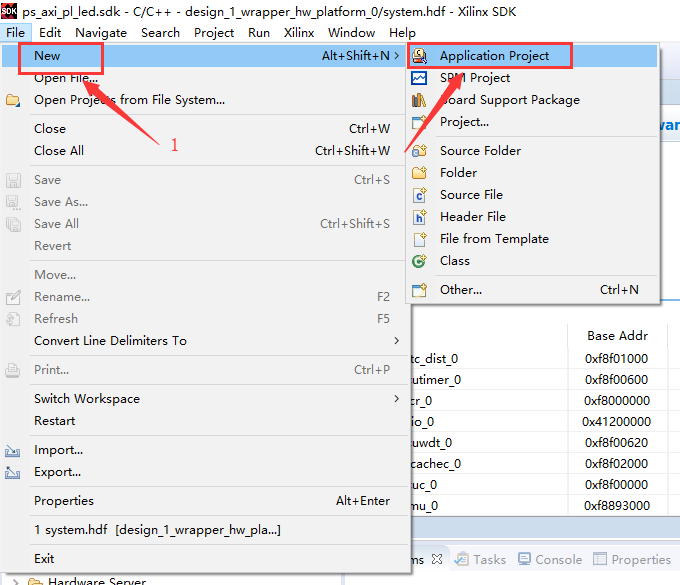
31file→new→Application Project,来新建一个“Application Project”,如下图所示。
32 给Application Project命名,最后点击“Next”,如下图所示。

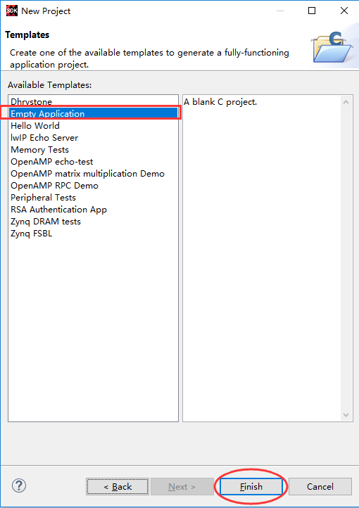
33选择“Empty Application”,然后点击“Finish”,如下图所示。
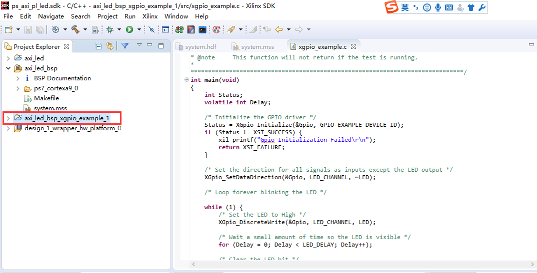
34axi_led_bsp→system.mss→import examples,在弹出的对话框中选择“xgpio_example”,最后点击“OK”确认,如下图所示。

35这样新建一个“xgpio_example”,如下图所示。
2.5、下载调试
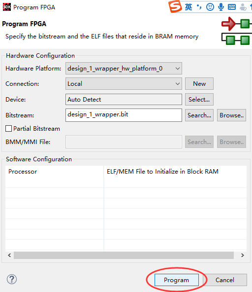
36design_1_wrapper_hw_platform0→Program FPGA,在弹出的对话框中选择默认,点击“program”,如下图所示;第一次下载可能会失败,第二次下载就成功了,这样就完成了bit文件的下载。
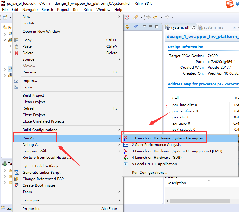
37axi_led_bsp_xgpio_example_1→Run As→1 Launch on Hardware(System Debugger),
2.5、实验总结
38下面是实验测试结果的视频,可以看到4个led在闪烁。(由于视频上传不了,只有个图片)

2.6、备注及疑问
40注意这里的DDR3并不是和板子上的DDR3严格对应,而是参数最接近的型号,有时候实验不通的话,问题往往出现在这里,可以多试几个。
41第一次下载可能会失败,第二次下载就成功了,这样就完成了bit文件的下载。
2.7、参考资料
1. cource_s1_ALINX_ZYNQ(AX7010_AX7020)开发平台基础教程V1.09
2. https://blog.csdn.net/q416524389/article/details/83865266
3. https://blog.csdn.net/weixin_39813867/article/details/83512913
文章转载自: https://www.cnblogs.com/ahead-liuyayong/p/10689021.html