本文转载自:OpenFPGA微信公众号
可编程逻辑系统通常部署在可能存在噪声的应用中。这种噪声会影响可编程逻辑设计接收的信号。例如,它可能会导致信号故障或跳动,如果处理不当,可能会导致设计和操作出现问题。
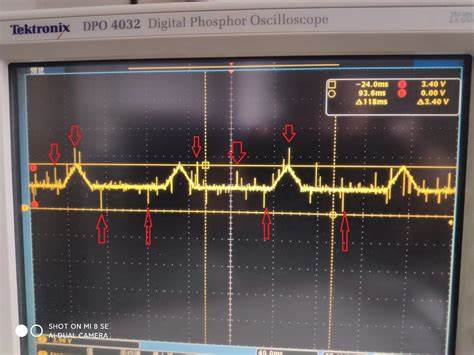
毛刺的持续时间是随机的,并且与时钟沿不同步。因此,它们可能会导致下游信息损坏。
处理此问题的最常见方法是使用毛刺滤波器来滤除毛刺和反弹。
毛刺滤波器核心是使用长度可变的移位寄存器,噪声信号被放到寄存器中,直到移位寄存器的所有值都一致。此时,信号可以视为稳定。当然,我们必须确定潜在毛刺和反弹可能持续多长时间,以确保时钟周期的寄存器大小正确。这就是为什么我们的毛刺滤波器需要非常灵活,并且需要确保其大小能够适合每个应用程序的要求。
滤波器应该能够接收噪声输入并滤除持续时间为多个时钟脉冲的毛刺。

library ieee;
use ieee.std_logic_1164.all;
use ieee.numeric_std.all;
entity glitch_filter is
generic(
G_FILER_LEN : integer := 8
);
port(
i_clk : in std_ulogic;
i_noisy : in std_ulogic;
o_clean : out std_ulogic
);
end glitch_filter;
architecture behaviour of glitch_filter is
signal s_delay_line : std_ulogic_vector(G_FILER_LEN - 1 downto 0);
signal s_delay_and : std_ulogic;
signal s_delay_nor : std_ulogic;
signal s_output_clean : std_ulogic;
begin
o_clean <= s_output_clean;
--Delay disctete using delay line
synchroniser_process : process (i_clk) begin
if rising_edge(i_clk) then
s_delay_line <= s_delay_line(G_FILER_LEN - 2 downto 0) &
i_noisy;
end if;
end process;
--Generate AND and NOR of delay line bits
s_delay_and <= '1' when to_01(s_delay_line) =
(s_delay_line'range => '1') else '0';
s_delay_nor <= '1' when to_01(s_delay_line) =
(s_delay_line'range => '0') else '0';
--Set discrete based on delay line
output_process : process (i_clk) begin
if rising_edge(i_clk) then
if s_delay_nor = '1' then
s_output_clean <= '0';
elsif s_delay_and = '1' then
s_output_clean <= '1';
end if;
end if;
end process;
end behaviour;
为了测试这个模块,创建一个简单的测试文件,它将随机数量的毛刺注入信号中。在信号改变状态后,许多随机毛刺被输入到信号中。如果滤波器运行正常,则这些毛刺将在毛刺滤波器输出干净的信号。
library ieee;
use ieee.std_logic_1164.all;
use ieee.numeric_std.all;
use ieee.math_real.all;
entity glitch_filter_tb is
end;
architecture bench of glitch_filter_tb is
component glitch_filter
generic (
G_FILER_LEN : integer
);
port (
i_clk : in std_ulogic;
i_noisy : in std_ulogic;
o_clean : out std_ulogic
);
end component;
-- Clock period
constant clk_period : time := 10 ns;
-- Generics
constant G_FILER_LEN : integer := 8;
-- Ports
signal i_clk : std_ulogic :='0';
signal i_noisy : std_ulogic;
signal o_clean : std_ulogic;
begin
i_clk <= not i_clk after (clk_period/2);
glitch_filter_inst : glitch_filter
generic map (
G_FILER_LEN => G_FILER_LEN
)
port map (
i_clk => i_clk,
i_noisy => i_noisy,
o_clean => o_clean
);
uut : process
variable glitch_duration : integer;
variable seed1 : positive := 1;
variable seed2 : positive := 283647823;
impure function integer_random(min, max : integer) return integer is
variable random : real;
begin
uniform(seed1, seed2, random);
return integer(round(random * real(max - min) + real(min)));
end function;
begin
i_noisy <= '0';
wait until rising_edge(i_clk);
wait for G_FILER_LEN * clk_period;
test: for i in 0 to 1 loop
i_noisy <= '1';
wait until rising_edge(i_clk);
glitch_duration := integer_random(1,5);
for x in 0 to glitch_duration loop
i_noisy <= not i_noisy;
wait until rising_edge(i_clk);
end loop;
i_noisy <= '1';
wait for 20 * clk_period;
report "loop high completed" severity note;
i_noisy <= '0';
wait until rising_edge(i_clk);
glitch_duration := integer_random(1,5);
for x in 0 to glitch_duration loop
i_noisy <= not i_noisy;
wait until rising_edge(i_clk);
end loop;
i_noisy <= '0';
wait for 20 * clk_period;
report "loop low completed" severity note;
end loop;
report "Simulation complete" severity failure;
end process;
end;
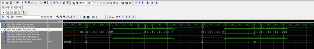
运行仿真后显示在信号状态改变后随机数量的脉冲便增加。检查输出信号表明滤波器已正确滤除输入信号中可能存在的毛刺。
正如在一开始所说的,这样的滤波器对于部署在可能存在电噪声的环境中非常有用。与 BRAM 上的 EDAC 等其他缓解策略相结合,这是可用于实现设计弹性的关键方法之一。