作者: 数字站
从最初学FPGA到现在,遇到过太多bug,但都没有写过博客记录,因为多数问题都比较简单且网上有比较好的答案。
但最近发现一个布局布线的报错,并不是因为逻辑导致的,而是用户不清楚布局布线导致的,且网上基本上相关的解答,因此把原因分析出来。
相关问题报错
[Place 30-719] Sub-optimal placement for a global clock-capable IO pin-IDELAY-BUFG pair. If this sub optimal condition is acceptable for this design, you may use the CLOCK_DEDICATED_ROUTE constraint in the .xdc file to demote this message to a WARNING. However, the use of this override is highly discouraged. These examples can be used directly in the .xdc file to override this clock rule.
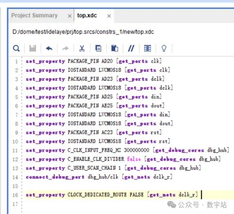
< set_property CLOCK_DEDICATED_ROUTE FALSE [get_nets dclk_r] >
u_IDELAYE2 (IDELAYE2.DATAOUT) is locked to IDELAY_X0Y78
and dclk_r_BUFG_inst (BUFG.I) is provisionally placed by clockplacer on BUFGCTRL_X0Y1。

图1 place 30-719报错
按照错误提示,在xdc中添加如下约束,然后重新综合、布局布线。
然后出现如下错误,很多人可能会直接出现下面的错误,原因都是一样的。
[Place 30-650] Non IO buffer dclk_IBUF_BUFG_inst{BUFG} is driving IDATAIN pin of IDELAY instance u_IDELAYE2. This will lead to unroutable situation. IDATAIN pin of IDELAY instance should always get signal from IO buffer or GND.
[Place 30-99] Placer failed with error: 'Implementation Feasibility check failed, Please see the previously displayed individual error or warning messages for more details.'
Please review all ERROR, CRITICAL WARNING, and WARNING messages during placement to understand the cause for failure.
[Common 17-69] Command failed: Placer could not place all instances

复现错误
//--###############################################################################################
//--#
//--# File Name    : top
//--# Designer    : 数字站
//--# Tool      : Vivado 2017.4
//--# Design Date  : 2024
//--# Description  :
//--# Version    : 0.0
//--# Coding scheme  : GBK(If the Chinese comment of the file is garbled, please do not save it and check whether the file is opened in GBK encoding mode)
//--#
//--###############################################################################################
module top (
    input                  clk        ,//系统时钟信号;
    input                  rst        ,//系统复位信号,高电平有效;
    input                               dclk        ,//串行时钟输入;
    input                        din        ,//输入数据;
    output reg                      dout       //输出数据信号;
);
    reg     [9 : 0]                     din_r       ;

    wire                                dclk_r      ;
    wire                                clk_200m    ;

    //例化锁相环,生成idelaye2需要的200MHz时钟信号;
    clk_wiz_0 u_clk_wiz (
        .clk_out1   ( clk_200m  ),// output clk_out1
        .reset      ( rst       ),// input reset
        .clk_in1    ( clk       ) // input clk_in1
    );

    (* IODELAY_GROUP = "IODELAY_0" *) // Specifies group name for associated IDELAYs/ODELAYs and IDELAYCTRL
    IDELAYCTRL u_IDELAYCTRL (
        .RDY    (           ),// 1-bit output: Ready output
        .REFCLK ( clk_200m  ),// 1-bit input: Reference clock input
        .RST    ( rst       ) // 1-bit input: Active high reset input
    );

    //例化idelaye2对时钟信号进行延时24*78+600=24.72ns;
    (* IODELAY_GROUP = "IODELAY_0" *) // Specifies group name for associated IDELAYs/ODELAYs and IDELAYCTRL
    IDELAYE2 #(
        .CINVCTRL_SEL           ("FALSE"    ),//Enable dynamic clock inversion (FALSE, TRUE)
        .DELAY_SRC              ("IDATAIN"  ),//Delay input (IDATAIN, DATAIN)
        .HIGH_PERFORMANCE_MODE  ("FALSE"    ),//Reduced jitter ("TRUE"), Reduced power ("FALSE")
        .IDELAY_TYPE            ("FIXED"    ),//FIXED, VARIABLE, VAR_LOAD, VAR_LOAD_PIPE
        .IDELAY_VALUE           (24         ),//Input delay tap setting (0-31)
        .PIPE_SEL               ("FALSE"    ),//Select pipelined mode, FALSE, TRUE
        .REFCLK_FREQUENCY       (200.0      ),//IDELAYCTRL clock input frequency in MHz (190.0-210.0, 290.0-310.0).
        .SIGNAL_PATTERN         ("CLOCK"    ) //DATA, CLOCK input signal
    )
    u_IDELAYE2 (
        .CNTVALUEOUT    (               ),//5-bit output: Counter value output
        .DATAOUT        ( dclk_r        ),//1-bit output: Delayed data output
        .C              ( clk_200m      ),//1-bit input: Clock input
        .CE             ( 1'b1          ),//1-bit input: Active high enable increment/decrement input
        .CINVCTRL       ( 'd0           ),//1-bit input: Dynamic clock inversion input
        .CNTVALUEIN     ( 'd0           ),//5-bit input: Counter value input
        .DATAIN         ( 'd0           ),//1-bit input: Internal delay data input
        .IDATAIN        ( dclk          ),//1-bit input: Data input from the I/O
        .INC            ( 'd0           ),//1-bit input: Increment / Decrement tap delay input
        .LD             ( 'd0           ),//1-bit input: Load IDELAY_VALUE input
        .LDPIPEEN       ( 'd0           ),//1-bit input: Enable PIPELINE register to load data input
        .REGRST         ( rst           ) //1-bit input: Active-high reset tap-delay input
    );

    //移位输出数据;
    always@(posedge dclk_r)begin
        {dout,din_r[9:0]} <= {din_r[9:0],din};
    end

    //ila使用延时前的时钟采集din_r的数据;
    ila_0 u_ila_0 (
        .clk    (dclk   ),// input wire clk
      .probe0 (din_r  ) // input wire [9:0] probe0
    );

    //ila使用延时后的时钟采集din_r的数据;
    ila_0 u_ila_1 (
        .clk    (dclk_r ),// input wire clk
      .probe0 (din_r  ) // input wire [9:0] probe0
    );

endmodule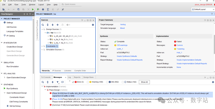
//--###############################################################################################
//--#
//--# File Name    : top
//--# Designer    : 数字站
//--# Tool      : Vivado 2017.4
//--# Design Date  : 2024
//--# Description  :
//--# Version    : 0.0
//--# Coding scheme  : GBK(If the Chinese comment of the file is garbled, please do not save it and check whether the file is opened in GBK encoding mode)
//--#
//--###############################################################################################
module top (
    input                  clk        ,//系统时钟信号;
    input                  rst        ,//系统复位信号,高电平有效;
    input                               dclk        ,//串行时钟输入;
    input                        din        ,//输入数据;
    output reg                      dout       //输出数据信号;
);
    reg     [9 : 0]                     din_r       ;

    wire                                dclk_r      ;
    wire                                clk_200m    ;

    //例化锁相环,生成idelaye2需要的200MHz时钟信号;
    clk_wiz_0 u_clk_wiz (
        .clk_out1   ( clk_200m  ),// output clk_out1
        .reset      ( rst       ),// input reset
        .clk_in1    ( clk       ) // input clk_in1
    );

    (* IODELAY_GROUP = "IODELAY_0" *) // Specifies group name for associated IDELAYs/ODELAYs and IDELAYCTRL
    IDELAYCTRL u_IDELAYCTRL (
        .RDY    (           ),// 1-bit output: Ready output
        .REFCLK ( clk_200m  ),// 1-bit input: Reference clock input
        .RST    ( rst       ) // 1-bit input: Active high reset input
    );

    //例化idelaye2对时钟信号进行延时24*78+600=24.72ns;
    (* IODELAY_GROUP = "IODELAY_0" *) // Specifies group name for associated IDELAYs/ODELAYs and IDELAYCTRL
    IDELAYE2 #(
        .CINVCTRL_SEL           ("FALSE"    ),//Enable dynamic clock inversion (FALSE, TRUE)
        .DELAY_SRC              ("IDATAIN"  ),//Delay input (IDATAIN, DATAIN)
        .HIGH_PERFORMANCE_MODE  ("FALSE"    ),//Reduced jitter ("TRUE"), Reduced power ("FALSE")
        .IDELAY_TYPE            ("FIXED"    ),//FIXED, VARIABLE, VAR_LOAD, VAR_LOAD_PIPE
        .IDELAY_VALUE           (24         ),//Input delay tap setting (0-31)
        .PIPE_SEL               ("FALSE"    ),//Select pipelined mode, FALSE, TRUE
        .REFCLK_FREQUENCY       (200.0      ),//IDELAYCTRL clock input frequency in MHz (190.0-210.0, 290.0-310.0).
        .SIGNAL_PATTERN         ("CLOCK"    ) //DATA, CLOCK input signal
    )
    u_IDELAYE2 (
        .CNTVALUEOUT    (               ),//5-bit output: Counter value output
        .DATAOUT        ( dclk_r        ),//1-bit output: Delayed data output
        .C              ( clk_200m      ),//1-bit input: Clock input
        .CE             ( 1'b1          ),//1-bit input: Active high enable increment/decrement input
        .CINVCTRL       ( 'd0           ),//1-bit input: Dynamic clock inversion input
        .CNTVALUEIN     ( 'd0           ),//5-bit input: Counter value input
        .DATAIN         ( 'd0           ),//1-bit input: Internal delay data input
        .IDATAIN        ( dclk          ),//1-bit input: Data input from the I/O
        .INC            ( 'd0           ),//1-bit input: Increment / Decrement tap delay input
        .LD             ( 'd0           ),//1-bit input: Load IDELAY_VALUE input
        .LDPIPEEN       ( 'd0           ),//1-bit input: Enable PIPELINE register to load data input
        .REGRST         ( rst           ) //1-bit input: Active-high reset tap-delay input
    );

    //移位输出数据;
    always@(posedge dclk_r)begin
        {dout,din_r[9:0]} <= {din_r[9:0],din};
    end

    //ila使用延时前的时钟采集din_r的数据;
    //ila_0 u_ila_0 (
    //    .clk    (dclk   ),// input wire clk
    //  .probe0 (din_r  ) // input wire [9:0] probe0
    //);

    //ila使用延时后的时钟采集din_r的数据;
    //ila_0 u_ila_1 (
    //    .clk    (dclk_r ),// input wire clk
    //  .probe0 (din_r  ) // input wire [9:0] probe0
    //);

endmodule
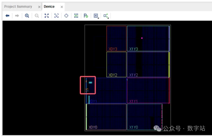
重新综合、实现工程后,在“IMPLEMENTATION”界面下双击“open Implemented Design”,如下所示。
在“Device”界面中找到DCLK引脚,如下图所示。
如下图所示,首先点击图中1处,就能查看芯片内部的实际走线了,如下图所示,左边为DCLK对应的管脚,信号进入管脚后,沿着绿色的走线,先到达idelaye2的输入,经过延时后输出到ILOGIC。
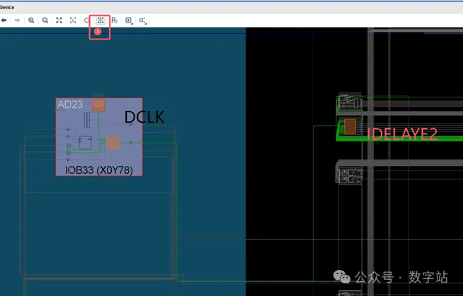
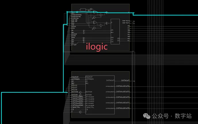
将上图中idelaye2和ilogic部分放大,如下图所示,蓝色走线是DCLK管脚输入,红色是idelaye2输出绕过ilogic进入FPGA内部逻辑的走线。
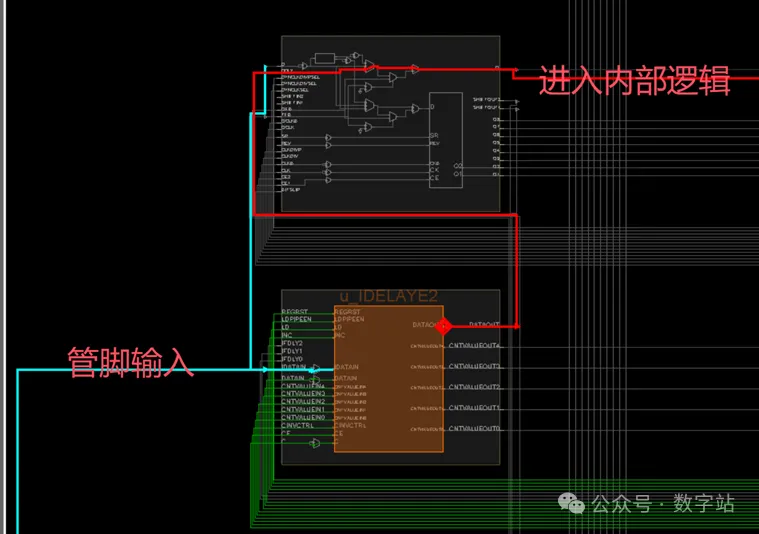
上述是输入信号进入FPGA管脚,经过idelaye2延时,绕过ilogic进入FPGA内部逻辑的走线。注意这部分是专用走线(固定不变的走线,只要使用idelaye2,不使用ilogic,走线就不会变),不是可编程的。
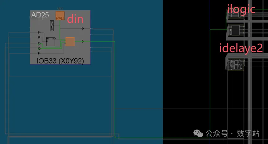
放大din在ilogic部分的走线,如下所示。din的管脚输入信号不经过idelaye2,同时绕过ilogic后输入到FPGA内部逻辑。
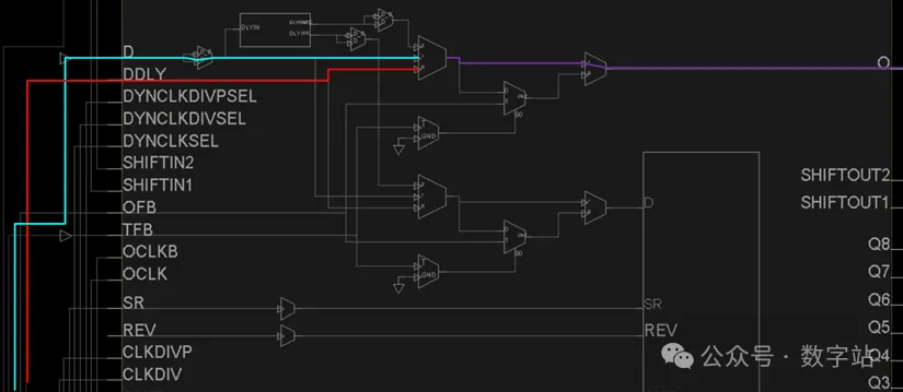
对比图8和图10就能找到前文出现错误的原因了。如果使用了经过idelaye2延时前后的同一个管脚输入信号,该如何走线?
如下图所示,在进入内部逻辑之前,都需要绕过ilogic。蓝色和紫色为idelaye2延时前的信号进入内部逻辑的走线,而红色和紫色为idelaye2延时后的信号进入内部逻辑的走线,紫色为两个信号重合的走线。
一根线不能同时传输两个信号,因此布局布线失败。
回到前文的问题,ila0使用了dclk没有经过idlaye2延时的信号作为时钟信号,而ila1使用dclk经过idelaye2延时后的信号作为时钟信号。
//--###############################################################################################
//--#
//--# File Name    : top
//--# Designer    : 数字站
//--# Tool      : Vivado 2017.4
//--# Design Date  : 2024
//--# Description  :
//--# Version    : 0.0
//--# Coding scheme  : GBK(If the Chinese comment of the file is garbled, please do not save it and check whether the file is opened in GBK encoding mode)
//--#
//--###############################################################################################
module top (
    input                  clk        ,//系统时钟信号;
    input                  rst        ,//系统复位信号,高电平有效;
    input                               dclk        ,//串行时钟输入;
    input                        din        ,//输入数据;
    output reg                      dout       //输出数据信号;
);
    reg     [9 : 0]                     din_r       ;

    wire                                dclk_r      ;
    wire                                clk_200m    ;

    //例化锁相环,生成idelaye2需要的200MHz时钟信号;
    clk_wiz_0 u_clk_wiz (
        .clk_out1   ( clk_200m  ),// output clk_out1
        .reset      ( rst       ),// input reset
        .clk_in1    ( clk       ) // input clk_in1
    );

    (* IODELAY_GROUP = "IODELAY_0" *) // Specifies group name for associated IDELAYs/ODELAYs and IDELAYCTRL
    IDELAYCTRL u_IDELAYCTRL (
        .RDY    (           ),// 1-bit output: Ready output
        .REFCLK ( clk_200m  ),// 1-bit input: Reference clock input
        .RST    ( rst       ) // 1-bit input: Active high reset input
    );

    //例化idelaye2对时钟信号进行延时24*78+600=24.72ns;
    (* IODELAY_GROUP = "IODELAY_0" *) // Specifies group name for associated IDELAYs/ODELAYs and IDELAYCTRL
    IDELAYE2 #(
        .CINVCTRL_SEL           ("FALSE"    ),//Enable dynamic clock inversion (FALSE, TRUE)
        .DELAY_SRC              ("DATAIN"   ),//Delay input (IDATAIN, DATAIN)
        .HIGH_PERFORMANCE_MODE  ("FALSE"    ),//Reduced jitter ("TRUE"), Reduced power ("FALSE")
        .IDELAY_TYPE            ("FIXED"    ),//FIXED, VARIABLE, VAR_LOAD, VAR_LOAD_PIPE
        .IDELAY_VALUE           (24         ),//Input delay tap setting (0-31)
        .PIPE_SEL               ("FALSE"    ),//Select pipelined mode, FALSE, TRUE
        .REFCLK_FREQUENCY       (200.0      ),//IDELAYCTRL clock input frequency in MHz (190.0-210.0, 290.0-310.0).
        .SIGNAL_PATTERN         ("CLOCK"    ) //DATA, CLOCK input signal
    )
    u_IDELAYE2 (
        .CNTVALUEOUT    (               ),//5-bit output: Counter value output
        .DATAOUT        ( dclk_r        ),//1-bit output: Delayed data output
        .C              ( clk_200m      ),//1-bit input: Clock input
        .CE             ( 1'b1          ),//1-bit input: Active high enable increment/decrement input
        .CINVCTRL       ( 'd0           ),//1-bit input: Dynamic clock inversion input
        .CNTVALUEIN     ( 'd0           ),//5-bit input: Counter value input
        .DATAIN         ( dclk          ),//1-bit input: Internal delay data input
        .IDATAIN        ( 'd0           ),//1-bit input: Data input from the I/O
        .INC            ( 'd0           ),//1-bit input: Increment / Decrement tap delay input
        .LD             ( 'd0           ),//1-bit input: Load IDELAY_VALUE input
        .LDPIPEEN       ( 'd0           ),//1-bit input: Enable PIPELINE register to load data input
        .REGRST         ( rst           ) //1-bit input: Active-high reset tap-delay input
    );

    //移位输出数据;
    always@(posedge dclk_r)begin
        {dout,din_r[9:0]} <= {din_r[9:0],din};
    end

    //ila使用延时前的时钟采集din_r的数据;
    ila_0 u_ila_0 (
        .clk    (dclk   ),// input wire clk
      .probe0 (din_r  ) // input wire [9:0] probe0
    );

    //ila使用延时后的时钟采集din_r的数据;
    ila_0 u_ila_1 (
        .clk    (dclk_r ),// input wire clk
      .probe0 (din_r  ) // input wire [9:0] probe0
    );

endmodule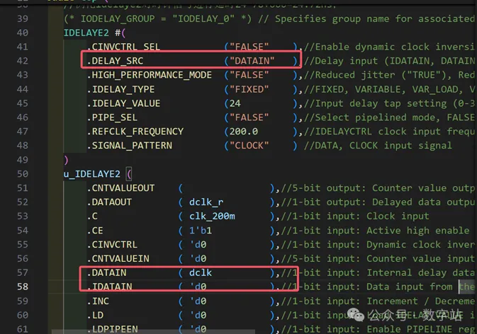
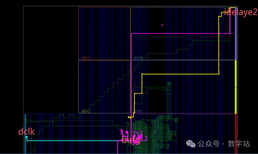
图12 idelaye2对内部信号延时
本文转载自:数字站
