作者:付汉杰,hankf@xilinx.com,文章转载自: 博客园
在Xilinx的ZCU102和ZCU106单板设计中,使用了管脚PS_MODE1作为外部USB Phy的复位信号。在MPSoC的文档ug1085和ug1087中,关于PS_MODE1的信息比较少。下面是更详细的描述。
1. UG1085文档
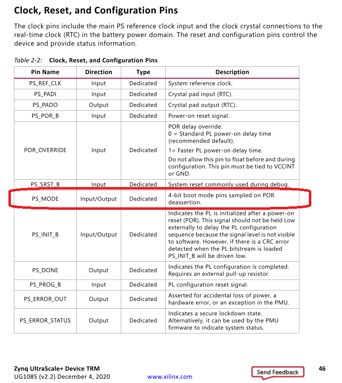
按UG1085,PS_MODE1本来作为MPSoC的启动模式管脚。
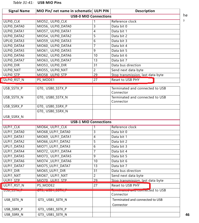
UG1085也提到,PS_MODE1/PS_MODE2也可以作为外部USB Phy的复位信号。
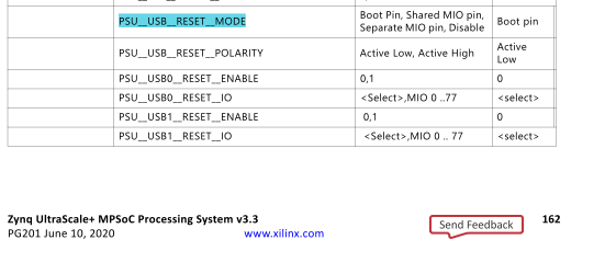
PG201也提到了外部USB Phy的复位信号的相关设置。
2. Vivado工具
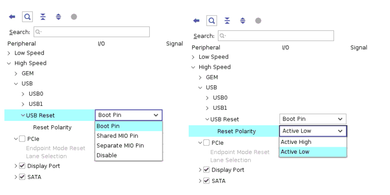
在Vivado里,可以指定外部USB Phy的复位信号的来源和极性。
3. USB Phy的复位信号
USB Phy是否需要复位信号,由外部的Phy决定。一般来说,单板复位后,建议把外部USB Phy复位一次,保证USB Phy处于干净的状态。
MPSoC既可以使用MIO管脚、也可以使用PS_MODE(BOOT_PIN)管脚来作为USB Phy的复位信号。
3.1. 使用MIO管脚作为USB Phy复位信号
MPSoC有两个USB控制器。如果都使用,外部有两个USB Phy。使用MIO管脚作为USB Phy复位信号时,可以两个USB Phy共用一个MIO(Shared MIO pin);也可以每个USB Phy使用一个MIO(Separate MIO pin)。
在Vivado里,配置对应的MIO作为对应的USB Phy复位信号。Vivado导出HDF/XSA文件时,会导出这些信息。
同时,在device tree里,添加下列字段。
xlnx,phy-reset-gpio = < &gpio GPIO_NUMBER GPIO_ACTIVE_HIGH/ GPIO_ACTIVE_LOW>;
USB驱动程序里,会查找参数“xlnx,phy-reset-gpio”。如果找到,会调用Linux的GPIO框架来复位外部USB Phy。
3.2. 使用PS_MODE管脚作为USB Phy复位信号
如果使用PS_MODE管脚(BOOT_PIN),则可以节约MIO管脚;在device tree里,也不用添加参数。
FSBL里,会使用PS_MODE的对应寄存器,复位外部USB Phy。文件psu_init.c里,可能有下列代码。
/*##################################################################### */

    /*
    * BOOT PIN LOW
    */
    /*
    * Register : BOOT_PIN_CTRL @ 0XFF5E0250

    * Value driven onto the mode pins, when out_en = 1
    *  PSU_CRL_APB_BOOT_PIN_CTRL_OUT_VAL                           0X0

    * When 0, the pins will be inputs from the board to the PS. When 1, the PS
    *  will drive these pins
    *  PSU_CRL_APB_BOOT_PIN_CTRL_OUT_EN                            0X2

    * Used to control the mode pins after boot.
    * (OFFSET, MASK, VALUE)      (0XFF5E0250, 0x00000F0FU ,0x00000002U)
    */
	PSU_Mask_Write(CRL_APB_BOOT_PIN_CTRL_OFFSET,
		0x00000F0FU, 0x00000002U);
/*##################################################################### */

    /*
    * ADD 5US DELAY
    */
		mask_delay(5);

/*##################################################################### */

    /*
    * BOOT PIN HIGH
    */
    /*
    * Register : BOOT_PIN_CTRL @ 0XFF5E0250

    * Value driven onto the mode pins, when out_en = 1
    *  PSU_CRL_APB_BOOT_PIN_CTRL_OUT_VAL                           0X2

    * When 0, the pins will be inputs from the board to the PS. When 1, the PS
    *  will drive these pins
    *  PSU_CRL_APB_BOOT_PIN_CTRL_OUT_EN                            0X2

    * Used to control the mode pins after boot.
    * (OFFSET, MASK, VALUE)      (0XFF5E0250, 0x00000F0FU ,0x00000202U)
    */
	PSU_Mask_Write(CRL_APB_BOOT_PIN_CTRL_OFFSET,
		0x00000F0FU, 0x00000202U);
/*##################################################################### */
4. 单板定制
虽然ZCU102和ZCU106单板都使用了管脚PS_MODE1作为外部USB Phy的复位信号。客户的单板,可以自由选择PS_MODE和MIO作为外部USB Phy的复位信号。
5. 输出模式
PS_MODE1是totem-pole驱动,不是open-collector驱动。
6. 参考文档
SR #10480757 ZynqUS+ USB PHY reset feature