作者:Tulip Peng,来源:FPGA FAE技术分享选集微信公众号
接着上一篇“AMD Versal系列CIPS IP核介绍”文章来进一步讲解如何来建立CIPS IP核示例工程。
利用CIPS IP核的板卡自动化以及预置功能,生成VCK180 DDRMC基于GUI界面的调试工程。当然该工程亦可以根据AMD官网例程TCL文件来完成。
本文是基于Vivado 2022.1版本进行演示,其他版本界面可能会有细小差异。
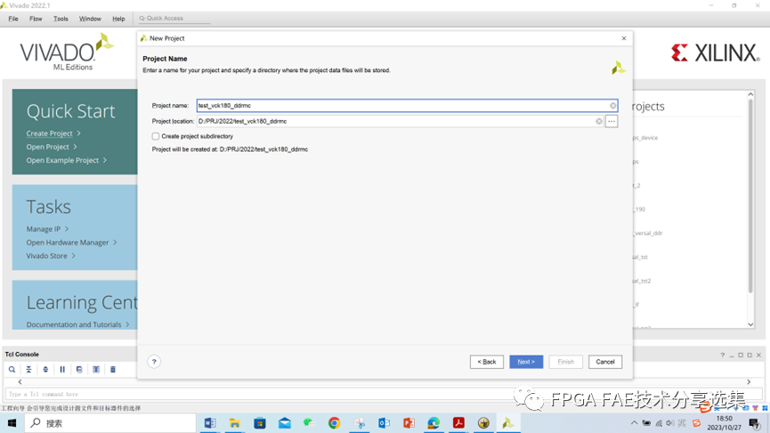
Step1 新建工程
工程名字和路径需要字符形式出现,同时路径不能太长。

Step2 选定工程板卡
由于我们是做DEMO目的,所以板卡选择Versal Prime系列的VMK180;当然也可以选择其他Versal系列的开发板,或者客户自定义。

Step3 创建Block Design工程
使用Block Design流程可以很方面的增减IP,给设计带来很高的灵活性并节约写代码时间。

Step4 加入CIPS IP核

Step5 运行Automation与预置功能


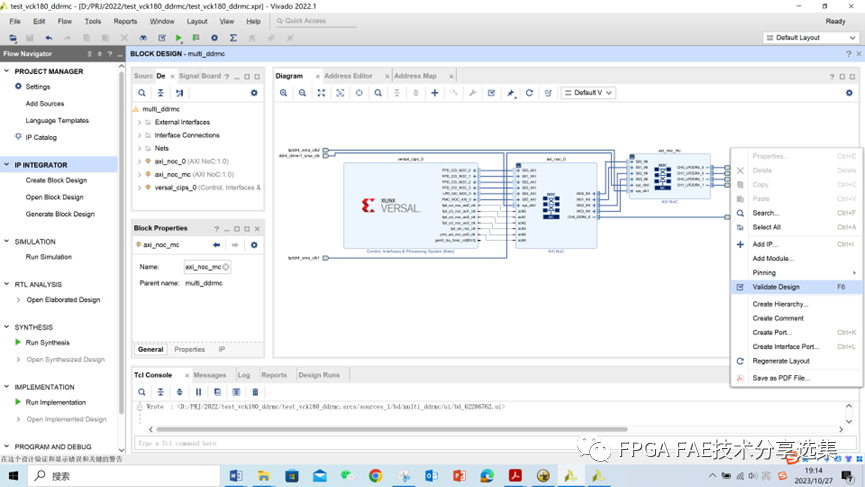
Step6 生成工程Diagram
Runing Automation可以自动生成CIPS的已定义的接口,同时可以跟其他IP进行互连,避免人工操作。


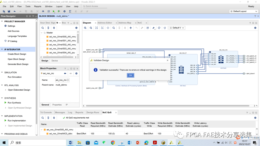
Step7 设计验证
运行Vaildate Design功能可以检查Block Design设计是否有误;需要把错误全部消除掉才可以进入下面流程。


Step8 生成HDL Wrapper

Step9 生成Device Image


Step10 成功生成Device Image


Step11 导出硬件平台

成功生成xsa文件后,软件工程师就可以使用xsa进行后续软件开发工作。
如果您对此文章内容感兴趣,欢迎联系:
simonyang@comtech.cn
charlesxu@comtech.cn