作者:Yin Chaowen,AMD工程师;来源:AMD开发者社区
1. Versal CPM QDMA EP Design 默认状态下的Setup Debug流程及debug core 时钟,以Vivado 2024.1为例。
1)创建Versal CPM QDMA EP Design Example Design。
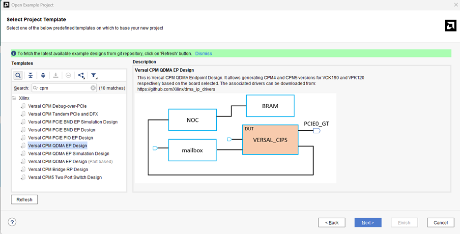

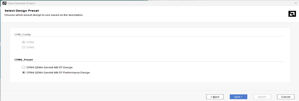
2)综合之后使用使用Setup Debug的方式创建ila core
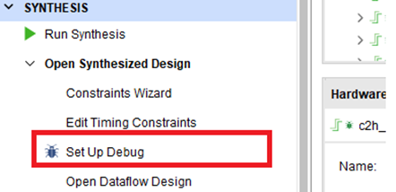
Clock Domain选择pcie0_user_clk,后续一直next,并保存xdc文件。
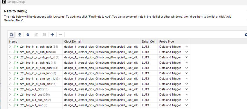
3)Run implementation、Generate Device Image,完成之后点击 Open Implemented Design.查看axi_dbg_hub的aclk连接到了pcie0_user_clk上(如下图)
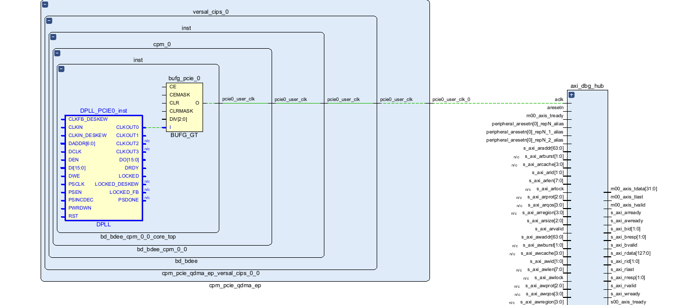
如果此时下载Generate Device Image生成的pdi和ltx,就会遇到如下的错误:
ERROR: [Xicom 50-233] Failed to setup debug cores: Error reading hub static info at address 0x3FFC0000000: Connection timed out
ERROR: [Xicom 50-300] Failed to communicate with debug hub address(es): 0x3ffc0000000
Resolution:
1. Verify Probes File(s) corresponds to currently programmed PDI.
2. Make sure debug hub(s) and debug core(s) are accessible and their communication paths are not blocked.
INFO: [Labtools 27-1434] Device xcvc1902 (JTAG device index = 1) is programmed with a design that has no supported debug core(s) in it.
WARNING: [Labtools 27-3413] Dropping logic core with cellname:'u_ila_0' at location 'uuid_23E7D65A79BC59F7BC47406C1714DFAE' from probes file, since it cannot be found on the programmed device.
refresh_hw_device: Time (s): cpu = 00:00:00 ; elapsed = 00:00:06 . Memory (MB): peak = 9742.754 ; gain = 0.000
ERROR: [Common 17-39] 'refresh_hw_device' failed due to earlier errors.
错误的原因:
pcie0_user_clk 不是一个free-running的时钟,它仅用于在 PL(可编程逻辑)和 CPM(控制处理器模块)之间时钟逻辑。DPLL(数字锁相环)需要校准并锁定到预定的频率,连接到 PL 的路由也是 PDI 文件中嵌入的 PL 编程的一部分,因此不能保证在编程时该时钟处于运行状态。如果你需要一个自由运行的时钟,应该使用由 PS生成的 4 个 PL 时钟中的一个。你可以在 IPI(集成处理器接口)中时钟选项卡启用它们。
2. 修改Example Design。
1) 开启PS生成的4个PL时钟的一个给debug_hub使用。
修改CIPS的配置,使能PL Fabric Clocks -> PL CLK0,并设置位100M,使能之后再BD内的cips可以看到多了个pl0_ref_clk端口。pl0_ref_clk是free-running的clock。
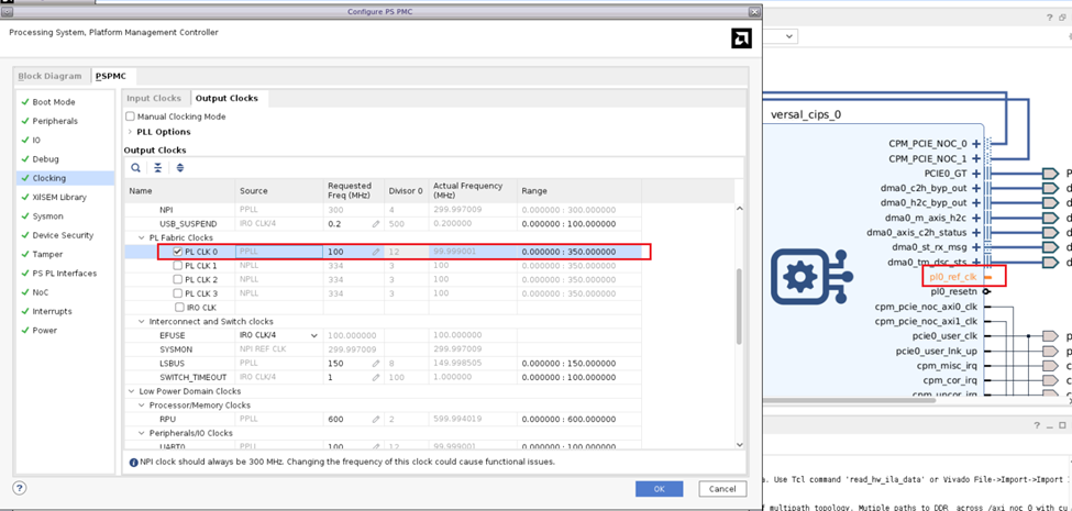
2) 修改设计之后并保存重新运行Synthesis、implementation、Generate Device Image.
等待Generate Device Image运行完毕之后,点击Open Implemented Desig,使能pl0_ref_clk之后,工具自动将debug_hub和u_ila_0的aclk连接到了pl0_ref_clk, u_ila_0还有个clk端口就是Setup debug clock domain对应的pcie0_user_clk。
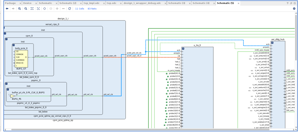
3) 下载修改过后的pdi和ltx.
等待Generate Device Image运行完毕之后,点击Open Implemented Desig,使能pl0_ref_clk之后,工具自动将debug_hub和u_ila_0的aclk连接到了pl0_ref_clk, u_ila_0还有个clk端口就是Setup debug clock domain对应的pcie0_user_clk。
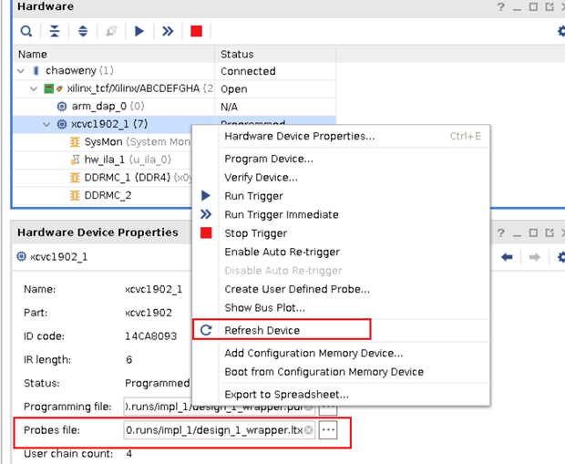
下载之后需要热重启host,并加载DMA的Driver。然后再open Hardware Manager,设设置好对应的ltx文件,并'refresh_hw_device就能看到ila窗口。
DMA Driver 链接 :